
How collection works
Particles acquire charge as they pass through an ionized region. The electric field drives charged particles toward collecting surfaces. Collected material must then be removed without excessive re-entrainment.
What determines performance
Important factors include gas flow, particle size, dust resistivity, gas temperature and moisture, available electrical power, collecting geometry, gas distribution and dust removal.
Dry and wet ESPs
Dry ESPs typically remove collected material by rapping. Wet ESPs use liquid washing and are suited to selected fine particulate and mist applications. The correct configuration depends on the process.
Why performance changes
A change in fuel, process chemistry, flow or temperature can change collection behavior even when the equipment appears mechanically unchanged. A systematic assessment connects those changes to measured emissions.
Detailed technical material
Photographs and technical illustrations
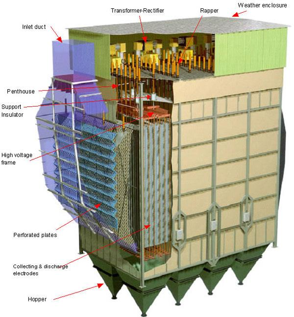
Electrostatic Precipitation
An Electrostatic Precipitator (ESP) is an air pollution control device that removes particles from a flowing gas with electric forces.
In another words, an electrostatic precipitator is a particle control device that uses electrical forces to move the particles out of the flowing gas stream and onto collector plates. The particles are given an electrical charge by forcing them to pass through a corona, a region in which gaseous ions flow. The electrical field that forces the charged particles to the walls comes from electrodes maintained at high voltage in the center of the flow lane. Once the particles are collected on the plates, they must be removed from the plates without re-entraining them into the gas stream. This is usually accomplished by knocking them loose from the plates, allowing the collected layer of particles to slide down into a hopper from which they are evacuated. Some precipitators remove the particles by intermittent or con-tinuous washing with water.
The electrical force acts for the most part on the particles and not the gas. Thus, the pres-sure drop is very low compared to other control options. ESPs are used in industry (for example, steel mills, pulp/paper plants, cement kilns, and waste incineration), coal-fired electric power plants, and indoors in homes and offices. The existence of electrostatic forces of attraction have been noted for centuries. However, it was not until 1907 that Dr. Frederick Cottrell designed the first ESP.
An ESP is designed for a particular industrial application. Manufacturers use various methods to design ESPs. They also consider a variety of operating parameters that affect collec-tion efficiency including resistivity, electrical sectionalization, specific collection area, aspect ratio, gas flow distribution, and corona power.
One of the difficulties confronting many of the world’s power stations is that they were designed with electrostatic precipitators at a time when emission limits were set at a level above those that are currently acceptable. In addition, the characteristics of coals that are presently be-ing used may well be different to those of the coals for which the plant was originally designed. Means of overcoming these difficulties in order to comply with reduced emission limits have been addressed in a number of ways, including (in the event that the end-result must meet strin-gent today’s or the future requirements) enlarging the precipitators, converting precipitators to the fabric filters/baghouses, or by employing different novel technologies. Alternatively, rela-tively simple, low cost flue gas additive (flue gas conditioning or FGC) to modify the character-istics of the dust and thus make it easier to collect have been adopted as a means of signifi-cantly improving the collection efficiency.
Particle collection in the ESP is disrupted if back corona occurs in the collected material. With high resistivity particles, localized areas of high electric field (due to high current flow) in the collected dust layer can cause electrical breakdown. Ions with polarity opposite to that of the corona on the wires then move into the gas stream where they reduce the charge on particles and may cause sparking. Back corona is associated with low-sulfur coals, which have relatively high resistivities. For this reason, many utilities in the southwestern U.S. use baghouses.
Recent trends in the design of ESPs for electric utilities focus on improved collection of low-sulfur/high-resistivity coal and cost reductions gained from saving energy and structural ma-terials. Innovations include wide plate spacing, intermittent energization, pulse energization, precharging, and microprocessor control of energization and rapping. In addition, several new novel technologies combining both electrostatic precipitator and baghouse in one common hous-ing is under development.
Nearly ninety percent of U.S. coal-fired utility boilers are equipped with electrostatic pre-cipitators (ESP). In recent years there had been increasing interest and activity related to improv-ing existing precipitators. The ESP technology is effective for capturing and controlling particu-late emissions down to 2.5 μκ dia. The challenge is to capture very fin particulates below this diameter, which are small enough to penetrate deep into the lings and threaten human health.
Before “diving” into the ESP technology discussion and review the possible upgrade/retrofit technologies, it might help to take a brief trip into the electrostat-ic precipitation history. The first US Patent on electro-static precipitation (No. 342,548) was issued to A. Q. Walker in 1886. Unfortu-nately, Mr. Walker’s device was unsuccessful, mainly due to an inadequate power supply. The first successful ESP was patented by Dr. Frederic Cottrell (No. 895,729) in 1908. He used the then newly developed synchronous mechanical rec-tifier and a high voltage AC transformer to produce DC power of 10 to 15 kV. His initial commercial units were used for the collection of sul-furic acid mist at a powder works in Pinole, California and a nearby smelter at Selby.
The success at Selby unit led Dr. Cottrell, in 1910, to install his third commercial ESP at the Balaklala smelter in Northern California to collect lead and zinc oxide fume. Application of the process was extended to the collection of cement kiln dust at Riverside, California in 1912 with the first unit installed on a PC fire utility boiler at Detroit Edison Co. in 1923.
Electrostatic precipitators use electrical fields to remove particulate from boiler flue gas. Because precipitators act only on the particulate to be removed, and only minimally hinder flue gas flow, they have very low pressure drops, and thus low energy requirements and operating costs.
In an electrostatic precipitator, an intense electric field is maintained between high-voltage discharge electrodes, typically wires, or rigid frames, and grounded collecting electrodes, typically plates. A corona discharge from the discharge electrodes ionizes the gas passing through the precipitator, and gas ions subsequently ionize dust (or other) particles. The elec-tric field drives the negatively charged particles to the collecting electrodes. Periodically, the collecting electrodes are rapped mechanically to dislodge collected particulate, which falls into hoppers for removal.
In a typical electrostatic precipitator, collecting plates are arranged parallel to the gas flow, normally 9-18 inches apart, with discharge electrodes between them. Most precipitators have 3-5 independent electrical sections, i.e., sets of discharge and collecting electrodes with in-dependent power supplies, in series. Each independent section removes a fraction of the particu-late in the gas stream. This arrangement allows the use of higher voltages in the first sections of the precipitator, where there is more particulate to be removed. Lower voltages must be used in the final, cleaner precipitator sections to avoid excessive sparking between the discharge and col-lecting electrodes. In a precipitator with only one electrical section, the power input would be limited to the input which would cause sparking at the precipitator exit, thus limiting the perfor-mance of the entire precipitator.
Precipitator sectionalization has the added advantage that particles re-entrained in the flue gas stream by rapping may be collected in downstream sections of the precipitator, thus minimiz-ing net rapping reentrainment losses.
While several factors determine electrostatic precipitator removal efficiency, precipitator size is of paramount importance. Size determines treatment time: the longer a particle spends in the precipitator, the greater its chance of being collected, other things being equal.
Precipitator size also is related to the specific collection area (SCA), the ratio of the sur-face area of the collection electrodes to the gas flow. Higher collection areas lead to better re-moval efficiencies. Collection areas normally are in the range of 200-800 ft²/1,000 acfm. In or-der to achieve collection efficiencies of 99+ %, specific collection areas of 350-400 ft²/1000 acfm are typically used with some larger installations reaching SCA’s of 600 and even up to 1,000 ft2/1,000 acfm. On the other hand, some older precipitators on utility boilers are small, with specific collection areas below 200 ft²/1,000 acfm and correspondingly short treatment times. Expansion of these precipitators, or their replacement with larger precipitators, can lead to greatly enhanced performance.
Maximizing electric field strength will maximize precipitator collection efficiency. Automatic voltage controllers are used to maintain an electric field strength as high as possible to ensure maximum particle charging and collection, consistent with preventing electrical break-down of the gas and sparking between the discharge and collecting electrodes, which would ex-tinguish the electric field. These controllers detect spark onset, and maintain voltages just below the level at which sparking would occur.
Factors limiting precipitator performance are flow non-uniformity and reentrainment. More uniform flow will ensure that there are no high gas velocity, short treatment time paths through the precipitator. Attaining flow uniformity also will minimize “sneakage,” or gas flows bypassing the electrical fields. Reentrainment of collected particles may occur during rapping. Proper rapper design and timing will minimize rapper reentrainment. Maintenance of appropri-ate hopper ash levels and of flow uniformity will minimize reentrainment of ash from the hop-pers.
A key determinant of electrostatic precipitator collection efficiency is the resistivity of the particles to be collected. Resistivity is the resistance of particles to the flow of electric cur-rent. Particles with resistivities in the range of 107-1010 Ohm-cm are amenable to collection with precipitators: these particles are easy to charge, and only slowly lose their charge once deposited on a collecting electrode. Particles with low resistivities (less than 107 Ohm-cm), on the other hand, loose their charge to a collecting electrode so rapidly that they tend not to adhere to the electrode, with the result that there will be high rapping reentrainment losses. Carbon black is an example of a low resistivity material.
Particles with high resistivity (greater than 1010 Ohm-cm) can be difficult to remove with a precipitator: such particles are not easily charged, and thus are not easily collected. High-resistivity particles also form ash layers with very high voltage gradients on the collecting elec-trodes. Electrical breakdowns in these ash layers lead to injection of positively charged ions into the space between the discharge and collecting electrodes (“back corona”), thus reducing the charge on particles in this space and lowering collection efficiency. Dust from the combustion of low-sulfur coal typically has a high resistivity, and thus is difficult to collect.
Electrostatic precipitator overall (mass) collection efficiencies can exceed 99.9% for “normal” “well behaved” dust resistivity, and efficiencies in excess of 99.5% are common (although requiring quite large real state/footprint). Precipitators with high overall collection efficiencies will have high collection efficien-cies for particles of all sizes, so that excellent control of PM10 may be achieved with well designed and operated electrostatic precipitators (again, assuming the resistivity of the dust collected is in the “normal, well behaved” region).
Precipitator collection efficiencies will be somewhat lower for particles with diameters near 0.3 microns (PM2.5). The reason for a minimum in collection efficiency for 0.3-micron particles is that both particle charge and the resistance of the gas to particle motion both increase with particle size. Near 0.3 micron, the particle charge is low enough and the resistance to particle motion is high enough that particles are collected rela-tively poorly. In practice, however, this effect means only that a precipitator with a 99.9% over-all mass collection efficiency will collect over 90% of 0.3-micron particles, and over 97-98% of all 0-5 micron particles.
Older electrostatic precipitators may show poor performance not only due to the particu-late properties, but also to the fact that they were “grossly” undersized by today’s standards. In addition to general deterioration of the precipitators, several design factors can lead to less-than-desired performance. These can include small size and consequent short treatment time and low specific collection area, non-uniform flow, and inadequate electrical control systems.
Options for improving the performance of existing precipitators begin with simple re-builds. These normally include the replacement of electrodes, rappers, and other internal ele-ments, and modernization of the precipitator power supply and control system. An upgraded control system allows for improved voltage control, so that the voltage in each field may be maintained at the highest level possible without sparking. Precipitator rebuilds also include im-provements to the ductwork, casing, and flow devices to improve the flow distribution, seal leaks, etc.
Replacement of electrodes typically is accompanied by an increase in the spacing be-tween collecting electrodes from nine to 12 or 18 inches. While using a wider plate spacing low-ers specific collection area, the ability to use higher operating voltages without sparking increas-es collection efficiency enough to more than compensate for this change.
Further performance improvements can be obtained by increasing precipitator size and specific collection area. Some older utility units have specific collection areas as low as 150 ft²/1000 acfm; increases to values near 400-600 ft²/1,000 acfm may be necessary in order to meet the new source performance level of 0.03 lb/MBtu. Specific collection area and treatment time may be done by increasing plate height, which allows maximum use of the existing casing. On the other hand, there is a limit to the extent to which plate height can be increased, as precipita-tors should be longer than they are wide for maximum performance. Better options for increas-ing treatment time and collection area are adding one or more electrical fields and increasing the length of the fields. Because these options require additional construction outside of the existing casing, they are more expensive.
New and emerging technologies may offer a simpler and better solutions, while maintain-ing the available system footprint and reducing the environmental risk.